UV Mapping (of a Cube)
Previous post was about creating a cube mesh. This post will show how a 2D image can be projected to a 3D model’s surface (aka UV Mapping).
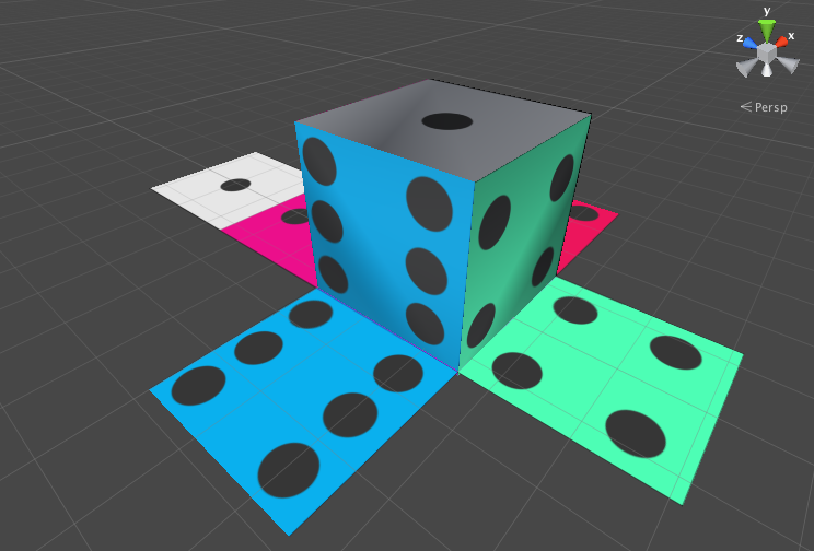
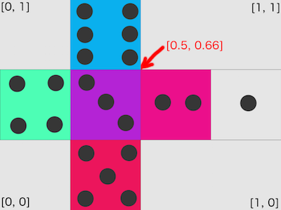
UVs are simply 2D coordinates that are used by 3D applications (in our case Unity3D) to map a texture to a model. The letters U and V were chosen because X, Y, and Z were already used to denote the axes of objects in 3D space. The U coordinate represents the horizontal axis of the 2D texture, and the V coordinate represents the vertical axis. Below is an unwraped image of a dice and the numbers are the UV coordinates.
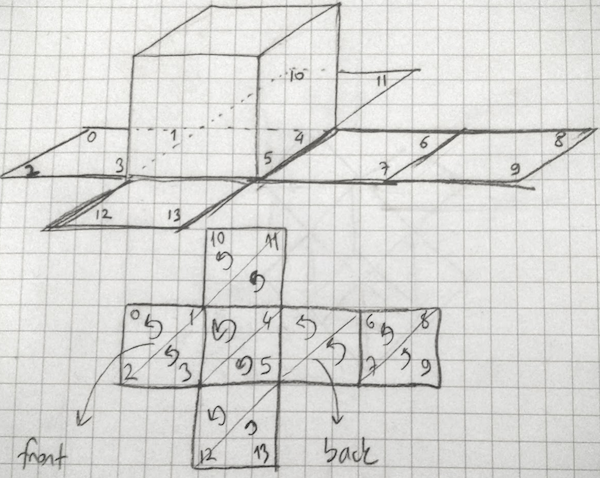
Normally UV Mapping is done by 3D tools. Making it manually is really complicated and hard to do. This is why I chose a cube which has a few vertices as an example. Below picture (a piece of art :) ) shows an unwrapped cube. The numbers from 0 to 13 are indices for vertices.
The mesh has an array of Vector2 which is called the uv array. The size of the UV array must be the same as the size of the vertices array. (14 in our cube example.) The arrow on each triangle shows the winding order which is counter clockwise, because we are looking inside of the cube which is not visible from the outside. Remember, Unity3D uses clockwise winding order for determining front-facing triangles.
Below code shows how to declare vertices, triangles and UVs. With this information Unity3D can render an unwrapped dice texture on top of our cube mesh.